Overview
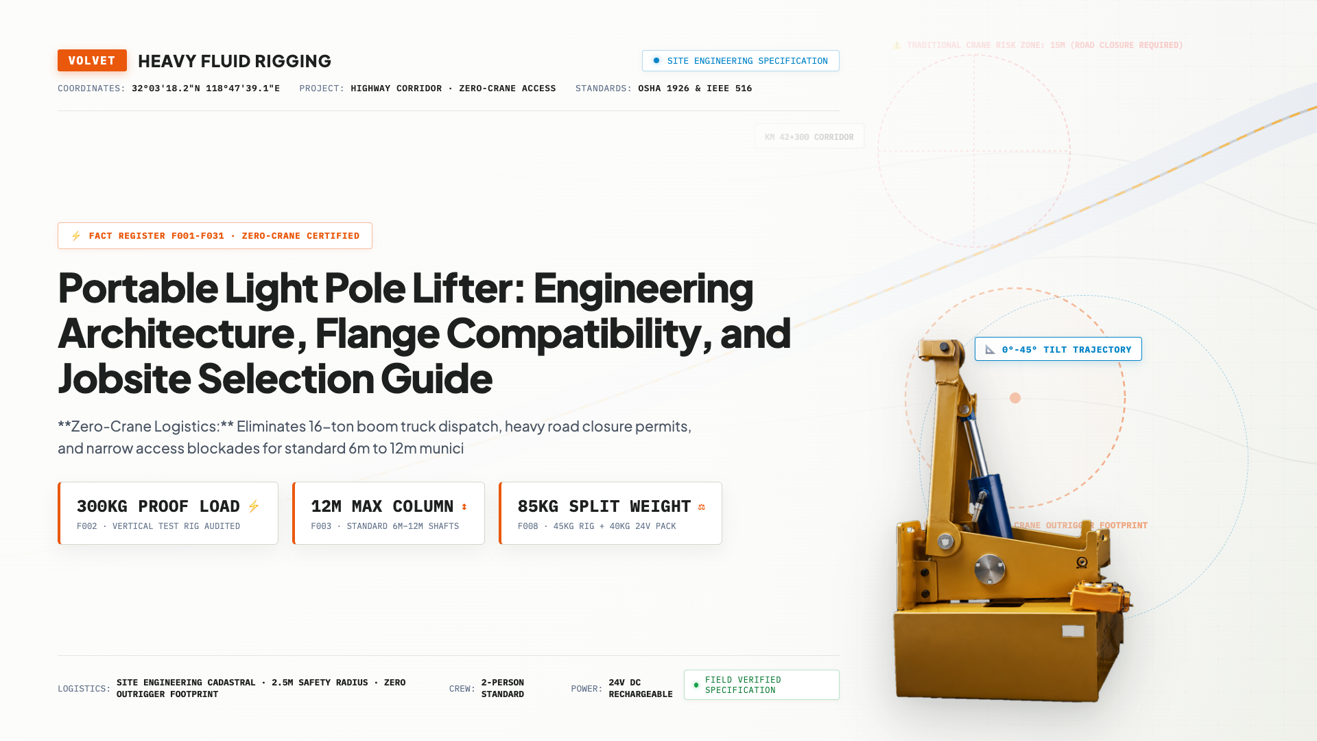
Erecting municipal street light poles has traditionally been synonymous with mobile crane dispatch. However, for standard 6m to 12m lighting columns on congested urban avenues, pedestrian walkways, and remote solar lighting corridors, scheduling a 16-ton boom truck introduces severe logistical friction, elevated mobilization charges, and extensive municipal permit waiting periods. As a result, civil contractors and electrical project engineers frequently evaluate whether it is technically feasible and structurally sound to install street light poles without a crane. This technical guide examines the structural physics, ground-level anchoring mechanics, equipment load baselines, and step-by-step execution protocols required to safely erect 12m lighting poles using portable hydraulic technology.
📌 Key Takeaways for Project Engineers
- Structural Feasibility: Safe crane-free erection in narrow access corridors relies on ground-level hydraulic leverage and foundation self-anchoring rather than overhead power hazards or cable suspension.
- Strict Load Boundaries: Rated capacity is strictly 300kg, verified on factory vertical test rigs to support standard municipal columns up to 12m.
- Two-Person Operational Protocol: Requires two workers utilizing an 85kg split-module system (45kg hydraulic cylinder + 40kg 24V power pack) for safe handling.
- Anchor Bolt Load Transfer: Universal base plate accommodates 180-260mm bolt patterns, transferring dynamic loads safely into ASTM F1554 foundation studs.
1. The Engineering Challenge of Crane-Free 12m Light Pole Erection
 02 / FEASIBILITY & COMPARISON
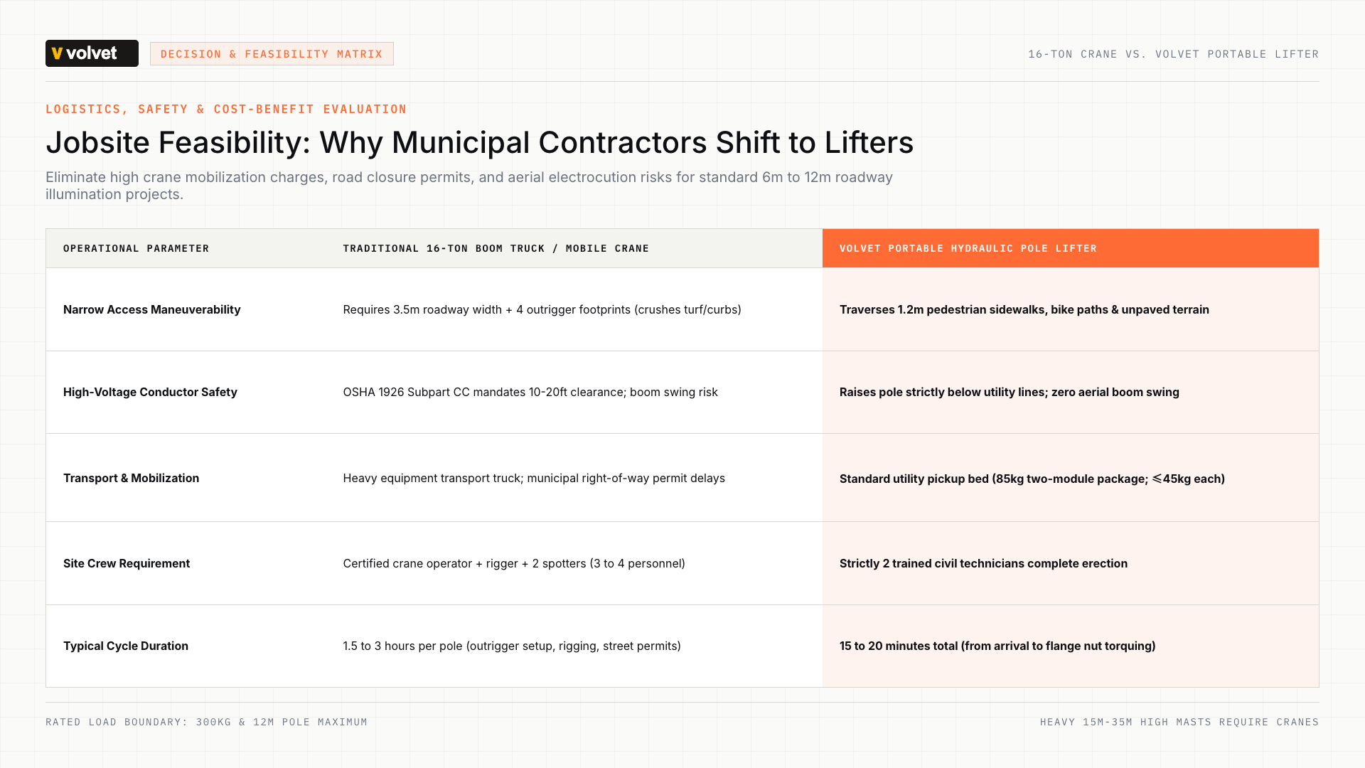
| Engineering Parameter | volvet Portable Pole Lifter | 16-Ton Mobile Boom Truck |
|---|---|---|
| Jobsite Access & Corridors | Narrow pathways, pedestrian walks, unpaved solar farms (zero roadway rutting) | Requires min 6m paved roadway width and firm ground for outrigger spread |
| Crew Size & Training | 2 trained workers (85kg modular transport in standard pickup) | 3–4 personnel (certified crane operator, rigger, signal person) |
| Overhead Electrical Clearances | Ground-level hydraulic hoist stays safely below powerlines (IEEE 516 / OSHA 1926) | High electrocution risk: requires OSHA 1926 boom clearances or shutoffs |
| Foundation Anchoring | Rigid self-anchoring to pre-embedded P.C.D. 180–260mm ASTM F1554 anchor cage | Relies on vehicular counterweights; high ground bearing pressures |
| Logistical Permits & Setup | May reduce municipal lane-closure permits; sets up in 15 minutes | Extended municipal permits, road closure notices, and multi-hour rental fees |
Erecting a 10m to 12m street light pole involves dynamic structural forces that differ significantly from simple vertical lifting. When a light pole lies horizontally on the ground prior to erection, the pivot point is located at the foundation base plate. Raising the column from zero degrees (horizontal) to ninety degrees (vertical) creates a varying angular moment:
- At the initial lift-off angle (0° to 15°), the required horizontal and vertical force vectors reach peak values due to the maximum horizontal distance between the pole center of gravity and the foundation pivot pin.
- As the pole passes 45 degrees, the required vertical lifting thrust decreases, but susceptibility to lateral wind gust deflection increases substantially.
- At full vertical orientation (90°), the pole must be held strictly plumb while base flange leveling nuts are torqued down.
Under ANSI/IES RP-8-18 roadway lighting guidelines, precise vertical alignment is mandatory to achieve calculated luminaire photometric spreads and avoid glare hotspots on driving lanes. Attempting to improvise crane-free installations using vehicle winches, ropes, or construction backhoes introduces extreme shock loads, uncontrolled swing arcs, and structural buckling hazards along the pole shaft. A purpose-engineered erecting system must provide rigid lateral guidance, metered hydraulic velocity, and continuous mechanical locking.
2. Two-Person Hydraulic Mechanics: 300kg Rated Load on Factory Test Rigs
 03 / MECHANICAL ARCHITECTURE
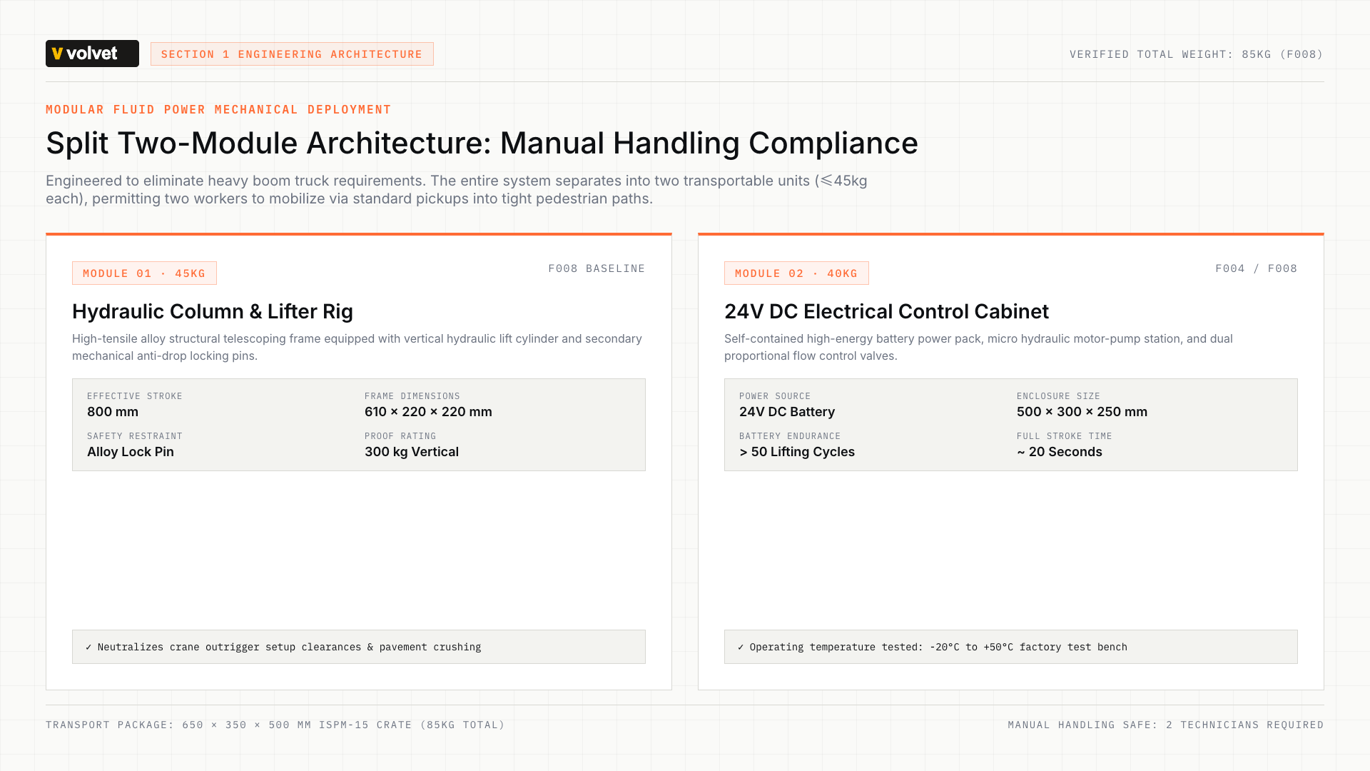
To provide the required lifting force without heavy support trucks, modern portable erecting systems utilize closed-circuit fluid power driven by an integrated 24V DC battery system. The hydraulic pump delivers high pressure to a heavy-wall alloy telescoping cylinder, generating consistent vertical thrust while drawing minimal electric current.
The structural capacity of the equipment is strictly verified at 300kg rated capacity. Every production machine is manufactured to strict vertical load specifications to ensure structural stability and counterbalance valve reliability.
Transportability is achieved through a split two-module architecture weighing 85kg in total:
- Hydraulic Lift Mast Assembly: 610 × 220 × 220 mm; weight: 45kg.
- 24V Electric Pump Cabinet: 500 × 300 × 250 mm; weight: 40kg.
- Packaged Outer Dimensions: 650 × 350 × 500 mm.
The split weight ensures compliance with international occupational manual handling thresholds, allowing two workers to move the equipment across curbs, sidewalks, and soft turf where boom trucks cannot tread.
When evaluating overall project delivery, contractors should review the portable pole jacks to cranes comparison to contrast site mobilization overhead with modular transport logistics.
3. Foundation Anchorage Mechanics: P.C.D. 180mm to 260mm and Bolt Shear Integrity
 04 / BASE & FLANGE COMPATIBILITY
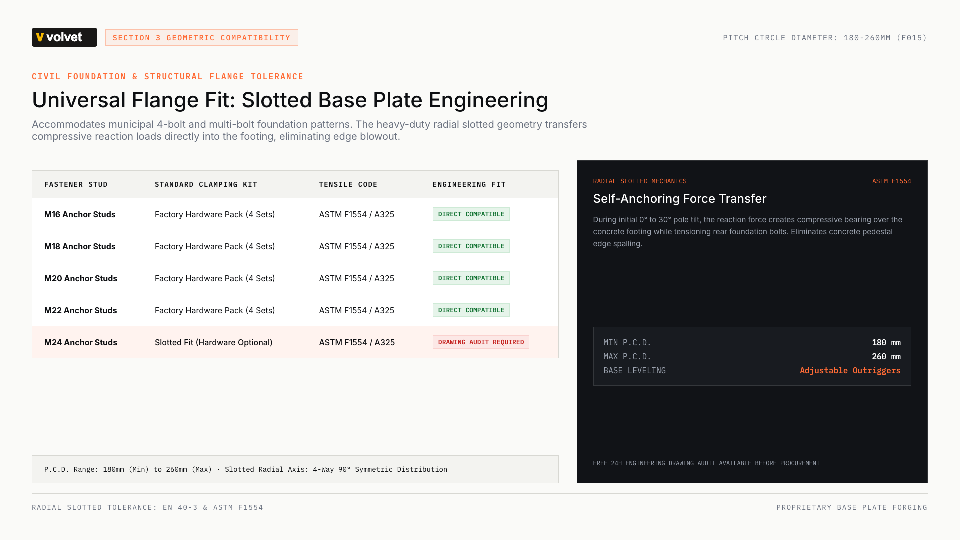
A critical safety principle of the portable pole lifter is self-anchoring. Rather than relying on heavy counterweights or wide vehicle outriggers that block traffic, the machine rigidly clamps directly onto the existing concrete footing's pre-embedded anchor cage.
Foundation anchor cages typically utilize structural steel anchor studs conforming to ASTM F1554 Grade 36, Grade 55, or Grade 105. During the initial lift-off stage, the erecting machine exerts a downward compressive reaction force on the front edge of the footing and a corresponding upward tensile reaction force on the rear anchor studs.
To accommodate municipal standard foundations across diverse regions, the lifter is equipped with a heavy slotted base plate supporting Pitch Circle Diameters (P.C.D.) from 180mm to 260mm:
- Stud Diameter Compatibility: Supports M16, M18, M20, M22, and M24 anchor bolts.
- Standard Packaging Hardware: Includes four sets of hardened mounting hardware each for M16, M18, M20, and M22 studs.
- M24 Project Verification: Compatible with the slotted base plate geometry; requires verification of thread pitch and projection height prior to site mobilization.
Project engineers should perform a base plate engineering review before fabrication to confirm stud projection, nut clearance, and edge distances against foundation calculation sheets.
Have a Custom Pole Flange or Tight Clearance?
Submit your destination, base plate dimensions, and foundation drawing for a prompt engineering compatibility review.
4. Step-by-Step Two-Worker Field Installation SOP
 05 / FIELD EXECUTION SOP
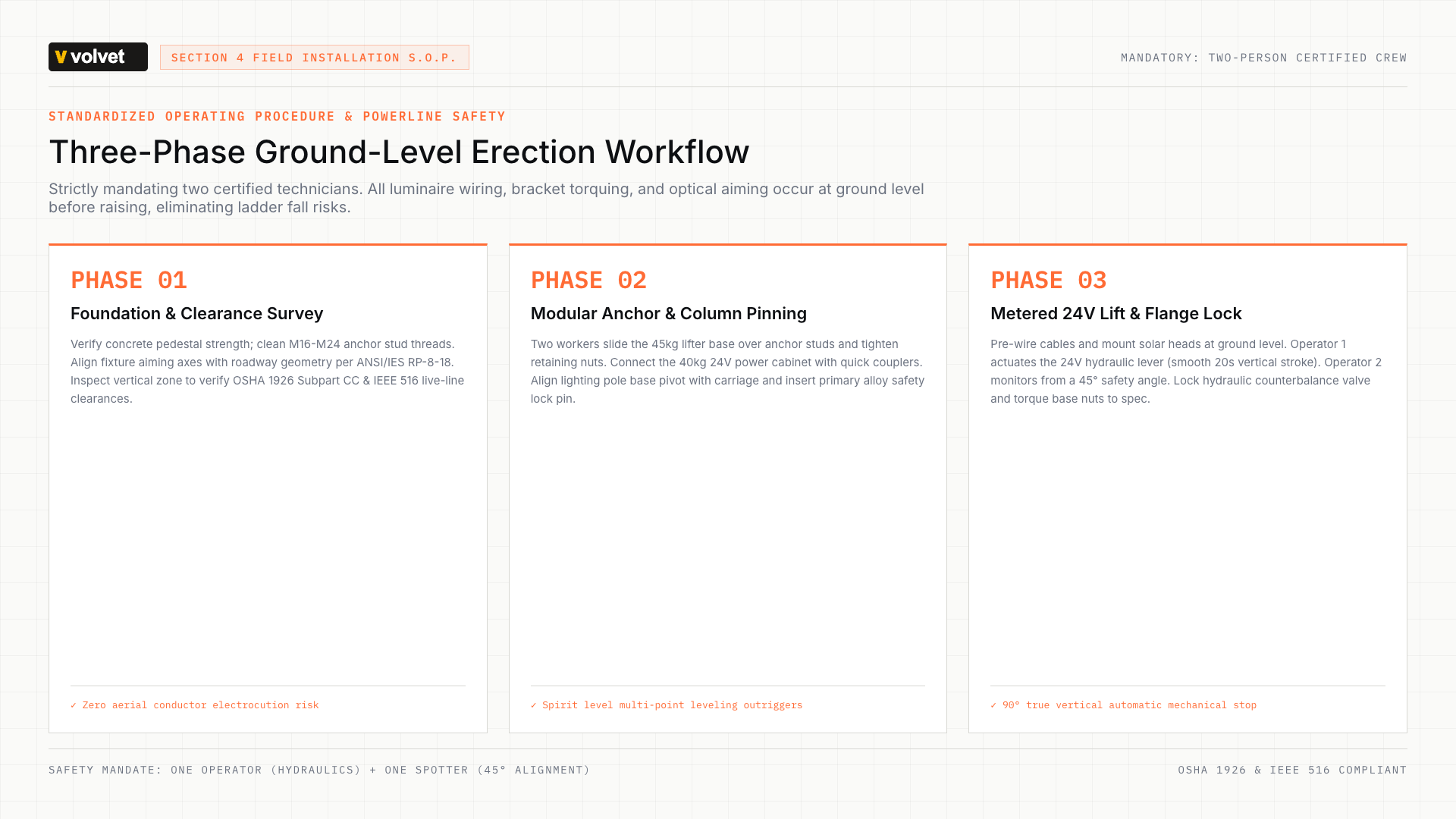
Safe and repeatable pole installation follows a disciplined, three-phase operational standard operating procedure (SOP). All work must be conducted by a qualified two-person crew.
Phase 1: Foundation Survey and Clearance Check
- Verify that concrete compressive strength has reached specified cure limits (minimum 28 days or formal cylinder test clearance).
- Clean anchor stud threads with a wire brush and verify level nuts are planar within 1.5mm across opposite studs.
- Check overhead airspace: Under OSHA 1926 Subpart CC (29 CFR 1926.1408), ensure that raising the 12m pole maintains required clearance buffers from any live overhead utility lines, preserving minimum approach distances aligned with IEEE 516 live-line safety guidelines.
Phase 2: Modular Assembly and Self-Anchoring
- Position the 45kg hydraulic lift mast assembly directly over the foundation cage and slide the slotted base plate over the exposed anchor studs.
- Engage foundation clamp washers and torque retaining nuts to prevent base plate slippage during the lift arc.
- Connect the 40kg 24V power pack using color-coded hydraulic quick-disconnect couplers.
- Adjust the leveling outriggers until the integrated circular bubble indicator confirms true vertical center.
Phase 3: Metered 24V Hydraulic Hoisting
- Pin the lower pole hinge bracket to the lifting carriage and secure the primary mechanical safety lock pin.
- Complete all luminaire wiring, bracket mounting, and optical aiming at ground level before initiating the lift.
- Worker 1 operates the directional hydraulic control valve, raising the pole at a steady, controlled rate (manufacturer-reported vertical cycle time: approximately 20 seconds).
- Worker 2 monitors the base plate pivot and stud alignment from a 45-degree safety observation angle.
- Once vertical alignment is reached, lower the pole flange onto the leveling nuts, thread upper structural nuts with lock washers, torque to specification, and disengage the erecting machine.
5. Jobsite Boundary Conditions: When Mobile Cranes Are Still Required
Engineering integrity demands recognizing the operational boundaries of portable hydraulic lifters. Compact erecting rigs are optimized for high-frequency, standard municipal lighting infrastructure; they are not universal replacements for mobile heavy-lift cranes.
Contractors must deploy conventional mobile boom trucks in the following project conditions:
- Total Assembly Weight Exceeds 300kg: Decorative cast-iron poles, high-mass luminaire arrays with heavy battery enclosures, or structural utility distribution poles exceeding the 300kg threshold.
- Pole Heights Exceeding 12m: Mid-mast and high-mast installations (15m to 35m) common at highway interchanges, sea container terminals, and sports stadiums.
- Severe Dynamic Wind Loads: In accordance with EN 40-3 structural standards, erection must be halted if ambient wind speeds exceed safe site thresholds (typically Beaufort Force 5 / 28 km/h), as wind moments on luminaire sail areas can challenge temporary rigging stability.
- Sub-Standard Foundation Concrete: Damaged anchor studs, crumbling pedestals, or unanchored temporary soil mounts where reaction clamping forces cannot be safely absorbed.
Frequently Asked Questions: Crane-Free 12m Pole Erection
What is the maximum pole height and weight capacity for crane-free erection?
The verified rated capacity is strictly 300kg vertical lifting load, designed for standard steel, aluminum, and composite lighting columns up to a maximum height of 12m. Poles exceeding 12m or 300kg must be erected using mobile cranes.
Can the equipment be safely operated by one worker?
No. Standard operating procedure strictly enforces a two-person operation crew. Even though the split package allows two workers to carry the 45kg and 40kg modules easily, one worker must operate the hydraulic control valve while the second technician guides base alignment and checks anchor bolt engagement.
Does the base plate accommodate square and circular bolt patterns?
Yes. The universal slotted base plate accommodates both 4-bolt square configurations and circular anchor cages with Pitch Circle Diameters (P.C.D.) between 180mm and 260mm, using M16, M18, M20, M22, or M24 studs.
What are the power requirements on remote jobsites?
The machine is powered by an onboard rechargeable 24V DC battery system. It requires no utility electrical connection, no three-phase AC generators, and produces zero exhaust emissions. Manufacturer specifications indicate over 50 lifting cycles per full charge under standard conditions.